The
Mars Exploration Rovers consists of twin probes
that are controllable rovers that move freely on the
surface of Mars. The rovers are:
- Spirit (MER-A)
- Opportunity (MER-B)
Spirit was launched on June 10, 2003 at 1:58 PM EST (Pad 17-A) and
landed on Mars on January 3, 2004. The Spirit
rover carries a memorial plaque dedicated to the
crew of the
Space Shuttle Columbia - the loss of the
Space Shuttle on February 2, 1003.
Opportunity was launched on July 7, 2003 at 11:18 PM EST (Pad 17-B) and
landed on Mars on January 24, 2004.
Both were launched from the Delta II rocket which was also responsible for launching all Mars related missions: Mars Global Surveyor in 1996, Mars Pathfinder in 1996, Mars Climate Orbiter in 1998, Mars Polar Lander in 1999, Mars Odyssey in 2001, and Mars Phoenix in 2007.

The tall object on the probe is the "pan-cam"
and is designed to be the height of an "average"
human so the proper perspective can be achieved.
Additionally, the wing like structure are the
solar panels, used to recharge the batteries.
While the mission was only expected to last a
few months, both probes are still operating!

The image above shows a self portrait by the
Spirit rover. The purpose of the rovers are to
examine closely the chemical makeup of the rocks
and soil. Special instruments on the rovers
include spectrometers and a rock cutting tools.
While the data is still being collected and
analyzed, the results are wonderful - water did
exist at some point on the Martian surface.
Week in Review slideshow of MER discoveries:
2004:
2005:
One Year Anniversary Slide Show
Some of the equipment used on the rovers are:
Alpha-Particle X-Ray Spectrometer
(from the MER Datasheets):
The Athena Alpha Particle X-ray
Spectrometer works by exposing martian materials
to energetic alpha particles and x rays from a
radioactive
244Cm
source, and then measuring the energy spectra of
backscattered alphas and emitted x rays. The
instrument is conceptually similar to the APXS
instrument that flew on the Mars Pathfinder
mission. However, there are several differences
that improve the instrumentÃs reliability and
performance. Unlike the Pathfinder APXS, the
Athena APXS does not have a proton mode. The
proton mode has been dropped because recent
increases in the spectral resolution and
sensitivity of the x-ray mode have made it
unnecessary. Significant modifications have also
been made to the instrument to reduce the CO2-induced
background that was observed on Pathfinder, to
improve x-ray spectral resolution, and to
decrease susceptibility to electromagnetic
interference. In addition, the Athena APXS will
undergo extensive preflight calibration under
Mars-ambient conditions, and will have two
onboard reference targets for postlanding
calibration on Mars.
The APXS instrument consists of
a sensor head mounted on the roverÃs Instrument Deployment Device, and electronics mounted in
the roverÃs Warm Electronics Box.
The sensor head contains six
244Cm
alpha radioactive sources with a total source
strength of about 30 mCi. The sources are each
covered with 3-μm aluminum foils that reduce the
energy of emitted alpha particles from the
initial value of 5.8 MeV to about 5.2 MeV. At
this energy, the alpha particle scattering cross
section of carbon is significantly reduced. The
reduction is accompanied by a slight degradation
of the alpha spectral resolution caused by
broadening of the excitation spectrum, but the
net result is a significant suppression of
atmospheric background in the alpha spectra.
Collimators in front of the sources define the
instrumentÃs field of view, which is about 38 mm
in diameter at the nominal working distance of
29 mm.
Surrounding the sources are six
thin alpha detectors. The FWHM for the alpha
mode of a
244Cm
peak at 5.8 MeV is less than 100 keV. Interior
to the ring of sources is a single
high-resolution silicon drift x-ray detector
with a 5-μm beryllium entrance window. The FWHM
of this detector at 6.4 keV is about 160 eV,
compared to 260 eV for the Pathfinder APXS. The
noise level in the x-ray mode will be less than
600 eV at temperatures below ñ30∞C, and the
efficiency at the 1.24 keV line of Mg will be at
least 20%.
Preamplifiers for both detector
channels and a circuit to generate detector bias
voltages are also mounted on the sensor head,
significantly reducing the instrumentÃs
susceptibility to electromagnetic interference.
The entrance to the detector
head is normally protected from martian dust and
other potential contaminants by a pair of doors.
These doors swing inward and lock open when the
sensor head is pressed against a target or other
hard surface. They can be closed again by
actuation of a release mechanism. The inner
surfaces of the doors provide a calibration
reference surface for the instrument. The sensor
head can also, if desired, be brought into
contact with the magnetite rich calibration
target designed for the Mˆssbauer spectrometer.
Signals from both detector channels
are processed by electronics mounted in the rover
WEB. Alpha signals from charge-sensitive
preamplifiers ñand similarly-x ray signals from a
customized voltage-sensitive preamplifiers in the
sensor head ñare further amplified and filtered
(semi-Gaussian pulse shapes) and then routed to peak
detectors, a multiplexer, and into a 16-bit A/D
converter for digitization. Signals from comparators
that trigger if signals exceed a preset level
initiate a sequence of logic signals necessary for
peak detection (sample gate and signal hold) and the
conversion process (program interrupt, alpha/x-ray
flags). A microcontroller selects the appropriate
input to the multiplexer and controls
analog-to-digital conversion. The analyzed events
are stored in the microprocessor buffer memory,
building up alpha- and x ray spectra.
The rover can place the APXS sensor
head in contact with rock surfaces or soil surfaces
at inclinations within the range of 0 to 90∞. Under
normal conditions, it should be possible to position
the instrument centerline within 0.4 cm of a target
location that has been observed by another IDD
instrument.
Proper preflight calibration is
essential to analysis of APXS data, so the Athena
APXS will undergo an extensive calibration program.
All calibration measurements will be made in a
chamber filled with a mixture of gases that closely
matches the composition of the martian atmosphere,
at the appropriate atmospheric density. Calibration
measurements will include:
-
spectral ìlibraryî
measurements of pure elements and oxides;
-
geochemical standards
that span the full range of plausible martian
surface compositions;
-
standard targets under
a range of atmospheric densities and measurement
geometries;
-
standard targets in
both natural and powdered form, to investigate
texture effects;
-
the APXS flight
calibration target;
-
the magnets of the
magnet array;
-
several blind certified
geochemical reference standards, for independent
assessment of the accuracy with which compositions
can be measured.
All of these measurements will be
made using the flight radiation sources.
The accumulation time for the APXS
will typically be at least 10 hours per sample
analysis, although significantly shorter durations
are possible when only the x-ray mode is used. Most
data accumulation will take place during the night
when the ambient martian temperature is the lowest,
giving the best energy resolution on all spectra.
However, it is desirable to break the total
accumulation time into several shorter accumulation
periods. The APXS can store up to 12 sets of
accumulated spectra and can transmit the data to the
rover either after each accumulation period, or all
sets of spectra at the end of the final accumulation
period.
The x-ray mode is sensitive to major
elements, such as Mg, Al, Si, K, Ca, and Fe, and to
minor elements, including Na, P, S, Cl, Ti, Cr, and
Mn. The alpha mode is sensitive to lighter elements,
particularly C and O. The depth of analysis varies
with atomic number, ranging from approximately 10 to
20 micrometers for sodium, to approximately 50 to
100 micrometers for iron. The detection limit is
typically 0.5 to 1 weight percent, depending on the
element. The APXS is insensitive to small variations
of the geometry of the sample surface because all
major and minor elements are determined, and can be
summed to 100 weight percent.
Back to Top
Microscopic Imager
(from the MER Datasheets):
The Athena Microscopic Imager (MI)
is a high-resolution imaging system mounted on the
IDD. The camera body is identical to the ones used
by Pancam, so the field of view is 1024 x 1024
pixels in size and the instrument has the same basic
radiometric performance characteristics as Pancam.
There is a single broad-band filter, so imaging with
the Microscopic Imager is monochromatic.
The MI optics employ a simple, fixed
focus design at f/15 that provides
3
mm depth-of-field at 30µm/pixel sampling. The field
of view is therefore 31â—Š31
mm at the working distance. The focal length is 20
mm, and the working distance is 63 mm from the front
of the lens barrel to the object plane. The
object-to-image distance is 100 mm. Preflight
geometric calibration will thoroughly characterize
the geometric distortion of the system.
The spectral bandpass of the MI
optical system is 400-680 nm. At best focus, the
modulation transfer function of the optics is at
least 0.35 at 30 lp/mm over this bandpass.
Radiometric calibration of the Microscopic Imager
will be performed with a relative (pixel-to-pixel)
accuracy of ≤5%,
and an absolute accuracy of
≤20%.
Calibration measurements will be obtained every 10
nm over the instrument's full spectral bandpass. The
MI signal to noise ratio will be at least 100 for
exposures of 20% full well over the spectral
bandpass and within the calibrated operating
temperature range (-55 to +5∫ C).
No onboard radiometric calibration
target is provided for inflight calibration of the
MI. It is likely that the MI will be able to view
the Compositional Calibration Target, and that this
target will provide fiducial marks that can be use
to perform a focus check. The MI will be able to
acquire unfocussed images of the martian sky,
providing flat fields.
The MI will be mounted on the
Instrument Deployment Device (IDD), allowing it to
be placed against surfaces that can also be examined
by the other Athena instruments. The IDD will have a
minimum controllable motion along a science target's
surface normal vector of 2}1
mm RMS, allowing it to image a rough surface in a
sequence of images. After placing the MI in position
for imaging, the motion of the IDD damps down to an
amplitude of less than 30 microns (i.e.,
less than one MI pixel) within 15 seconds. Whenever
the MI is not in use, the MI optics are protected
from contamination by a transparent cover. Preflight
calibration imaging will establish the transmission
properties of the cover. The cover is opened only
for MI imaging sequences. A contact sensor attached
to the MI will be used to detect rock and other hard
surfaces, to help ensure accurate positioning and
protect the MI from accidental damage.
The MI acquires images using only
solar or skylight illumination of the target
surface. Stereoscopic observations and mosaics can
be obtained by moving the MI between successive
frames. Stereo images and images taken at various
distances from the target will be used to derive the
3-dimensional character of the target surface.
Optical sections will also be combined to produce an
image of the target that is well-focused across the
entire frame.
Back to Top
Mini Thermal Emission Spectrometer
(from the MER Datasheets):
Mini-TES is a Michelson
interferometer that provides a spectral resolution
of 10 cm-1 over the wavelength range from 5-29 µm
(2000 - 345 cm-1). The instrument is mounted inside
the rover, and views the terrain around the rover by
using the PMA as a periscope. A scan mirror assembly
atop the PMA reflects radiation down through the PMA
and into the telescope and interferometer. The scan
mirror assembly allows Mini-TES to provide spectral
image cubes over a 360∞ range in azimuth and from
50∞ to +30∞ in elevation. The scan mirror assembly
also provides a view of internal and external,
full-aperture calibration targets. The elevation
mirror can be slewed to a stowed position in which a
cover blocks the Mini-TES aperture in the PMA,
protecting the optics from dust accumulation.
Mini-TES has two spatial resolution
modes. A solenoid-activated field stop can be
removed from the optical path to provide an IFOV of
20 mrad, or inserted to provide an IFOV of 8 mrad.
Baffles in the PMA define the stray energy field of
view and are designed to minimize stray energy from
outside the 20 mrad IFOV from entering the
interferometer. The inside of the PMA is designed to
minimize the stray background energy from the PMA
itself.
During data acquisition, the
PMAs elevation mirror and azimuth actuator are
sequenced to generate a raster image of the
scene. The scan mirror assembly can also be
commanded to allow Mini-TES to view the internal
and external calibration targets regularly in
order
to maintain instrument calibration during an
image acquisition. The elevation and azimuth
servos move and settle to each commanded
position ±1 mrad. Elevation steps of up to 20
mrad in size take place within the 200 msec
retrace period of the Mini-TES interferometer,
while azimuth steps may take as long as 1
second. Slews to the calibration targets take
significantly longer.
The Mini-TES telescope at the base
of the PMA is a reflecting Cassegrain configuration
with a mirror diameter of 6.35 cm, a focal ratio of
f/12, and an intermediate field stop that feeds an
approximately collimated beam into the Mini-TES
interferometer. The 6.35-cm telescope diameter
defines the minimum size of the Mini-TES beam; the
beam diverges further at an angle of either 8 or 20
mrad, depending on the resolution mode chosen. The
optical design provides for more than 85% of the
encircled energy to be contained in an
area equal to a single IFOV, 98% within an area
equal to 2 â—Š 2 IFOV, and 99.8% within an area equal
to 3 â—Š 3 IFOV. Focus is maintained from 2 meters to
infinity, with a blur of no more than 15% of an IFOV
at infinity focus.
The Mini-TES Michelson
interferometer uses the same flexure-mounted linear
motor mechanism and drive electronics as the Mars
Observer (MO)/Mars Global Surveyor (MGS) TES
instrument. The system uses a 980-nm interferometer
to generate interference fringes that control the
linear drive servo and time the acquisition of the
IR spectrometer data samples. The design is
simplified from the TES by combining the
infrared and visible counting interferometers into
one interferometer at one end of the motor drive and
replacing neon bulbs with redundant laser diodes.
Double-sided interferograms at a spectral resolution
of 10 cm-1 are obtained with a mirror travel
distance of 0.55 mm in 1.8 sec. A voltage ramp is
used to drive the mirror at a fixed velocity, and
position feedback is obtained from a linear voltage
displacement transducer. Optical switches sense
beginning of scan and synchronize the interferometer
with the elevation and azimuth drive motors.
Mini-TES uses a single uncooled
deuterated triglycine sulfate pyroelectric detector
sized to define the instruments 20-mrad IFOV. The
IFOV, dwell time, and interferometer scan rate have
been selected to produce frequencies in the range of
15 to 120 Hz which is
the range over which minimum noise equivalent
spectral radiance (NESR) can be achieved. The
detector provides the necessary performance over a
temperature range from 10 to +20∞C and with reduced
performance from 40 to +35∞C.
The NESR of the Mini-TES for a
single spectral accumulation interval at 10 µm
observing a scene at 270 K and 20 mrad will be <1.25
â—Š 10-8 W cm-2 sec-1 sr-1, corresponding to a
signal-to-noise ratio (SNR) of at least 450 for
co-addition of two observations. Radiometric
calibration of Mini-TES over its full spectral range
will be performed with an absolute accuracy of 5% or
better and a relative precision (pixel-to -pixel) of
2% or better, viewing a 270 K blackbody. The
internal calibration target is located inside the
head of the PMA, and the external target is located
on the deck of the rover. Both targets have
V-grooved surfaces and are coated with high
emissivity paint. Temperature sensors affixed to
both targets have an absolute accuracy of ±0.2∞C and
a precision of ±0.1∞C.
The instruments electronics are
based on the electronics of the MO/MGS TES. A 14.515
MHz internally-generated clock signal provides the
control timing for the interferometer motor
controller and synchronizes the scan timing and data
collection events with the
rover computer. Detection of start of scan by the
optical switches also signals to the rover computer
that data collection has begun. This signal triggers
an internal timer that initiates retrace of the
interferometer mirror after 1.8 seconds. Signals
from the detector
are fed through a pre-amplifier, variable gain
post-amplifiers for each field of view, an analog
multiplexer, a 16-bit A/D converter, and into an
output buffer.
Mini-TES begins collecting data at
the application of power. The instrument acquires
data in a cyclic fashion, with a period of two
seconds corresponding to the Michelson mirror scan
followed by its retrace. Spectral integration is
coordinated with the PMA elevation and azimuth drive
mechanisms using the rover computer. On each
two-second period (known as one ICK), the hardware
fills up the Mini-TES data buffer with header data,
interferogram data from the selected spectrometer
field of view, and the telemetry data.
Mini-TES flight software controls
the transfer of the data from the Mini-TES data
buffer to the rover CPU memory. Once the Mini-TES
data is available in the rover memory, the flight
software performs a Fourier transform on the
interferogram in order to generate a spectrum. It
then performs data aggregation in order to reduce
the total volume of data to be downlinked. Separate
programmable data aggregation modes in the spatial
domain (averaging spectra from consecutive ICKs) or
in the spectral domain (averaging data from
contiguous spectral points) are available. Data
volume is further reduced via lossless compression
using a Rice algorithm. Compressed data then
undergoes final formatting, packetization, and
transfer of the packets to rover data storage for
downlink.
The rover computer issues commands
to PMA motor driver circuitry in order to
synchronize the mirror movements to the Mini-TES
data acquisition. Direct commands from the rover
computer control instrument power and selectable
gain state, field of view, motor on/off, laser
heater on/off, redundant start-of-scan optical
switches, and redundant laser diodes.
Mini-TES operates primarily during
mid-day (10 a.m. to 3 p.m. local time) to obtain
high-quality spectral measurements of emitted
infrared energy. Nighttime observations may be
obtained to measure surface and atmospheric
temperatures of the full diurnal cycle for
thermophysical and boundary layer studies.
Back to Top
Mossbauer Spectrometer
(from the MER Datasheets):
The Athena Mˆssbauer spectrometer
uses a vibrationally-modulated 57Co source to
illuminate target materials. Backscattered gamma
signals are binned according to the source velocity,
revealing hyperfine splitting of 57Fe nuclear levels
that provides mineralogical information about the
target. The main parts of the instrument are the
Mˆssbauer drive that moves the 57Co source with a
well-known velocity, the γ- and x-ray detectors that
detect the backscattered radiation, the
microcontroller unit, the 57Co/Rh Mˆssbauer source,
and the radiation collimator and shielding.
The spectrometer is split into the
sensor head on the roverÃs Instrument Deployment
Device (IDD), and the electronics in the warm
electronics box (WEB). The sensor head carries the
Mˆssbauer drive with the analog part of the drive
control unit, the 57Co/Rh Mˆssbauer source, the
radiation collimator and shielding, the four PIN-
diode detector channels including pulse amplifiers,
and one reference detector channel to monitor the
velocity of the drive using a weak
57Co source and a well known Mˆssbauer reference
absorber in transmission geometry.
The WEB electronics consist of the
microcontroller and memories for data acquisition
and temporary storage. An extra FPGA logic unit
provides several functions for internal
communication, generates the velocity signal for the
drive, and contains fast pulse counters for
the detector signals. The WEB electronics also
contain voltage supply regulators and detector bias
voltage generators.
The analog signals of the five
detector channels are analyzed by discriminators for
14.4 keV and 6.4 keV peaks. Upper and lower
threshold values of the discriminators are generated
by digital to
analog converters (DACs). These values can be
changed automatically to follow the temperature
drift of the amplifiers. Digital signals from the
discriminators are sent to the velocitysynchronized
counters whenever a detected pulse is within the
specified range. Mˆssbauer spectra for the two
different energies of 6.4 keV and 14.41 keV are
sampled separately.
The Mˆssbauer spectrometer has its
own internal microcontroller, so that it can collect
data independently of the rover computer. Instrument
parameters are stored in a fault-tolerant fashion in
3 separate FRAMs and default values for these
parameters are taken from ROM in case of an error.
Every 60 minutes during a measurement, data is
stored into the EEPROM. In case of a failure of the
power supply, after restart of the instrument the
data acquisition will continue with this data. Each
Mˆssbauer spectrum consists of 512 ◊ 3-byte
integers. The pulses from the 4 counters are added
by hardware. Normally there is one spectrum for each
detector. The spectra are sampled into an SRAM of
128 Kbytes size.
Measurements are made by placing the
instrument directly against a rock or soil sample.
Physical contact is required to provide an optimal
measurement distance and to minimize possible
microphonics noise on the velocity-modulated energy
of the emitted γ rays. The mechanical construction
of the IDD and the interface limit vibration-induced
velocity noise at the sensor head to less than 0.1
mm/s. A contact plate is mounted at the front part
of the sensor head, assuring an optimal distance
from the sensor head to the sample of about 9 to 10
mm. A heavy metal collimator in front of the source
provides an irradiated spot of nominally 15 mm (up
to 20 mm, depending on actual sample distance and
shape) in diameter on the surface of the sample. The
IDD can position the instrument with an accuracy of
0.4 cm or better with respect to the position
observed by other IDD-mounted instruments. The
average depth of sampling by Mˆssbauer data is about
200 to 300 μm.
Mˆssbauer parameters are temperature
dependent. Especially for small particles exhibiting
superparamagnetic behavior (e.g., nanophase Fe
oxides), the Mˆssbauer spectrum may change
drastically with temperature. The observation of
such changes will help in determining the nature of
the iron-bearing phases. Therefore Mˆssbauer
measurements will be performed over a range of
diurnal temperatures spanning both the daytime
maxima and the nighttime minima.
One Mˆssbauer measurement takes
approximately 12 hours, depending on the phases
present in the sample and the total iron content.
The temperature variation for one spectral
accumulation interval will not be larger than about
±10∞C. When larger variations occur, spectra for
different temperature ranges are stored separately,
resulting in an increase in the total data volume
(depending on the number of temperature intervals
required), and a decrease of statistical quality
for the individual subspectra.
In parallel with the measurements of
samples, calibration spectra will be taken using the
reference channel implemented in the instrument. A
calibration target containing a thin slab of
magnetite-rich rock will also be included on the
rover where it can be viewed directly by the
instrument immediately after landing, as well as
later in the mission if necessary.
The performance of the Mˆssbauer
Spectrometer can be defined by measurements made in
transmission geometry with a Mˆssbauer source in
front of the instrument at a distance of 5 cm, and
in a backscattering geometry with the source
internal to the instrument in its flight
configuration. Instrument performance requirements
for such purposes are specified for a Mˆssbauer
source strength of 100 mCi for the backscattering
mode, 10ñ20 mCi for transmission mode, an
integration time of 10 minutes for the energy
spectra (backscattering and transmission), and an
integration time of 10 hours for the Mˆssbauer
backscattering spectrum.
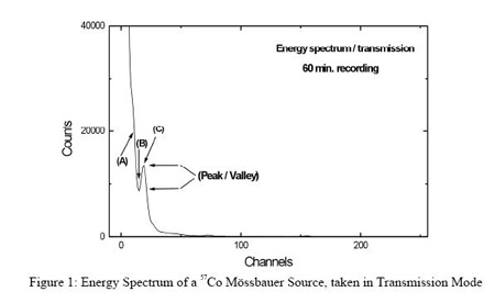
(1) Specifications for the energy
spectra taken in transmission mode (see Figure 1) at
a temperature of +20 (±1)∞C are:
-
noise level: The intensity at
(A) (channel 11) will not exceed 20.000 (±1000)
counts;
-
at (B) (ìvalleyî, channel 15),
the intensity will be less than 8900 (±500)
counts; and
-
the peak-to-valley ratio (ratio
of intensities at (C) (channel 19) and (B)) will
be equal to
or larger than 1.5.
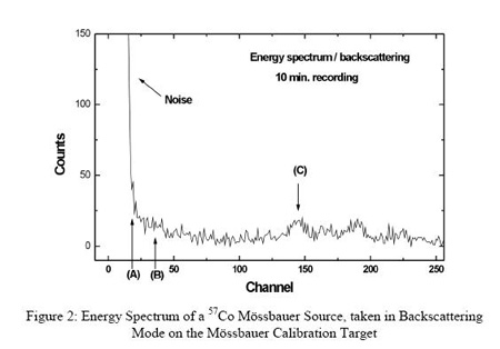
(2) Specifications for the energy
spectra taken in backscattering mode (see Figure 2)
at a temperature of +20 (±1)∞C are:
-
noise level: The intensity at
(A) (channel 18) will not exceed (50 ±10)
counts;
-
at (B) (channel 36) the
intensity will be less than 23 ±5 counts;
-
within the energy range channel
25 to channel 50 the intensity will be between 2
and 25 counts; and
-
at (C) (channel 145) the
tantalum X-ray line generated in the collimator
will be visible; the intensity will be 18 ±4
counts.
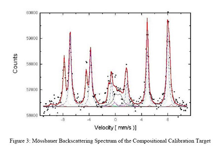
(3) Specifications for the Mossbauer
spectra taken in backscattering mode (bottom figure)
on its magnetite-rich calibration target at a
temperature of +20 (+/-1) degrees Celsius are that:
-
the peak/background ratio will
not be less than 1.11, as shown in Figure 3; for
a source activity between 80 and 120 mCi; and
-
the magnetite signal will be
visible with a peak/background ratio of not less
than 1.005.
Back to Top
Pancam
(from the MER Datasheets):
Pancam uses 1024â—Š2048 pixel Mitel
CCD array detectors developed for the MER Project.
The arrays are operated in frame transfer mode, with
one 1024â—Š1024-pixel region constituting the active
imaging area and the another adjacent 1024â—Š1024
region serving as a frame transfer buffer. The frame
transfer buffer has an opaque cover that prevents
>99% of light at all wavelengths from 400 to 1100 nm
from being detected by this region of the CCD. The
pixels are continuous, and the pitch is 12 μm in
both directions. The arrays are capable of exposure
times from 0 msec (to characterize the ìreadout
smearî signal acquired during the ~5 msec required
to transfer the image to the
frame transfer buffer) to 30 sec. Under expected
operating conditions, the arrays have at least
150,000 electrons of full-well depth, and a read
noise of less than 50 electrons. Dark current varies
with temperature; it is negligible at -55∞C and is
<1200 electrons/sec
at 0∞C. Analog to digital converters provide a
digital output with 12-bit encoding, and SNR > 200
at all signal levels above 20% of full scale. The
detector response has a linearity > 99% for signals
between 10% to 90% of full well.
Each array is combined with optics
and a small filter wheel to form one eye of a
multispectral, stereoscopic imaging system. The
optics for both cameras consist of identical
3-element symmetrical lenses with an effective focal
length of 38 mm and a focal ratio of f/20, yielding
an IFOV of 0.28 mrad/pixel and a square FOV of
16.8∞◊16.8∞ per eye. The optics and filters are
protected from direct exposure to the martian
environment by a sapphire window at the front of the
optics barrel. The optical design provides for more
than 90% of the encircled energy to be contained in
an area equal to 3â—Š3 IFOVs, and 99% in an area equal
to 5â—Š5 IFOVs, across the entire range of spectral
responsivity of the instrument and over the required
operating temperature range for performance of
Pancam within specifications (-55∞C to 0∞C). The
optical design allows Pancam to maintain optimal
focus from infinity to within about 1.5 meters of
the cameras. At ranges closer than 1.5 meters,
Pancam images suffer from some defocus blur. For
example, at a range of 80 cm (the approximate
distance from the Pancam calibration target), the
defocus blur is about 10 pixels.
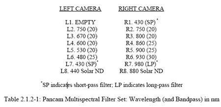
Each filter wheel has eight
positions, allowing multispectral sky imaging and
surface mineralogic studies in the 400-1100 nm
wavelength region. The left wheel contains one clear
(empty) position. The remaining filter wheel
positions are filled with narrowband interference
filters that are circular and 10 mm in diameter, and
that have the central wavelengths and bandpasses
listed in Table 2.1.2-1. One filter on each eye has
an ND5.0 coating to allow direct imaging of the Sun
at two wavelengths.
Radiometric calibration of both
Pancam cameras will be performed with an absolute
accuracy of 7% or better and a relative precision
(pixel-to-pixel) of 1% or better. Calibration will
be achieved using a combination of preflight
calibration data and inflight images of a Pancam
calibration target carried by the rover. The Pancam
calibration target is placed within unobstructed
view of both camera heads and will be fully
illuminated by the Sun between at least 10:00 AM and
2:00 PM local solar time for nominal rover
orientations. The target has three gray regions of
variable reflectivity (approximately 20%, 40%, and
60%) and four colored regions (peak reflectance in
the blue, green, red, and near-IR) for colorimetric
calibration. It includes a vertical post that will
cast a shadow simultaneously across all three gray
surfaces at some time within the 10:00 AM to 2:00 PM
nominal operating range. The calibration target is
large enough that defocus
blur will not produce significant degradation of the
calibration images.
The two Pancam eyes are mounted on a
mast on the rover deck. The mast is referred to as
the Pancam Mast Assembly (PMA), and also includes
several key components for the Mini-TES. The PMA is
erected to the vertical position by a deployment
actuator at its base. The cameras are located on a
"camera barî with a boresight 180∞ from the Mini-TES
boresight. The rover navigation cameras (Navcams)
are also located on this same camera bar, and point
in the same direction as Pancam. The boresight of
the Pancam cameras is approximately 1.3 m above the
martian surface with the PMA in the deployed
position. The cameras are moved together by ±90∞ in
elevation using a geared brush
motor on the camera bar. The entire PMA head,
including the cameras, can be rotated 360∞ in
azimuth by a geared brush motor assembly. A separate
geared brush motor provides elevation actuation for
the Mini-TES elevation mirror assembly. Hard stops
are provided for all actuation axes.
The two Pancam eyes are separated by
30 cm horizontally and have a 1∞ toe-in. This
separation and toe-in provide an adequate
convergence distance for scientifically useful
stereo topographic and ranging solutions to be
obtained from the near-field (5-10 m) to
approximately 100 m from the rover. Pointing control
is <2∞ in azimuth and <1∞ in elevation. Pointing
knowledge relative to the hardstops is 0.1∞ over the
entire range of motion of Pancam.
Pancam will operate primarily during
the daytime to obtain high-quality measurements of
sunlight reflected off rock and soil surfaces and
airborne dust particles, as well as direct solar
images using the two ND filters. Twilight or
nighttime sky or astronomical object imaging may be
possible but has not been committed to by the
Project. The required
operating temperature range for performance of
Pancam within specifications is -55∞C to 0∞C.
Pancam will be commanded by and will
return digital data directly to the rover computer.
The computer provides the capability to perform a
limited set of image processing tasks
on Pancam data prior to transmission. These tasks
include (1) bias and dark current subtraction, (2)
electronic shutter effect correction, (3) bad pixel
replacement, (4) rudimentary automatic exposure
control capability to maximize the SNR of downlinked
data while preventing data saturation, (5) image
subsampling and subframing, and (6)
image compression using a JPL-developed wavelet
compression algorithm called ICER.
Pancam telemetry is collected by the
rover computer and downlinked according to an
overall priority queue scheme agreed upon in advance
by the MER Science Operations Working Group. Image
data are packetized, with each packet containing
sufficient information to allow receipt in any order
and to allow incremental image reconstruction
even in the event of typical transmission errors and
packet losses.
Back to Top
Rock Abrasion Tool
(from the MER Datasheets):
The Rock Abrasion Tool (RAT) will be
used to penetrate through dust and surface
alteration that might be present on rocks, exposing
materials more likely to preserve evidence of
environmental
conditions at the time of their formation. The fresh
surfaces exposed can then be characterized by all of
the Athena instruments. The RAT is a diamond-tipped
grinding tool capable of removing a cylindrical area
4.5 cm in diameter and at least 0.5 cm deep from the
outer surface of a rock. This operation takes about
2 hours for a dense basalt.
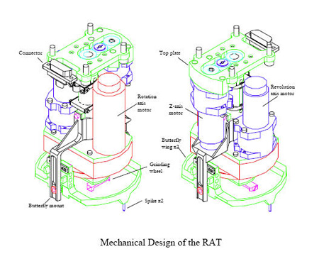
The RAT has a total of three
actuators (see figure). One causes each of two
grinding wheels to rotate at high speeds. Each of
these grinding wheels has two teeth, which cut out a
circular area associated with each grinding head as
the head rotates. A second actuator causes the two
grinding wheels to revolve around one another at a
much slower rate, sweeping the two circular cutting
areas around the full 4.5-cm diameter cutting
region. Finally, a third ìz-axisî actuator
translates the entire cutting head toward the rock,
causing it to penetrate to the commanded depth.
In order to grind a rock, the IDD
places the RAT directly against it. Contact is made
on two small spikes external to the grinding heads,
and a ring surrounding the heads can adjust in two
orthogonal axes to the orientation of the rock
surface. Once pressed firmly against the rock by the
IDD, all further actuations take place within the
RAT itself. Rotation and revolution of the grinding
wheels is initiated, and they are slowly translated
toward the rock surface by the z-axis actuator until
contact is made. Encoders monitor penetration
progress, and allow closed-loopcontrol of the
grinding process. A dust skirt around the cutting
surfaces helps to prevent release of dust that might
contaminate instruments.
The RAT is designed to preserve
petrologic textures of the prepared rock surfaces as
fully as possible, so that they can be viewed
effectively using the MI. The grinding process is
slow enough that no measurable modification of rock
chemistry or mineralogy by frictional heating is
anticipated. The grinding wheels are designed so
that contamination of the exposed surface by
cuttings from the rock (and previous rocks) is
minimized. Grinding wheel materials are selected
so that there should be no detectable contamination
of rock surfaces due to wear of the grinding heads
themselves.
During the operation of the RAT, the
rover will monitor currents, temperatures, and
encoder readouts for all three RAT actuators. These
data can be used to infer information about the
strength properties of the rocks that have undergone
grinding. A pre-flight test program is planned to
establish some of the relationships among these
parameters and rock strength, but this program will
be limited in scope. Further post-launch testing
with an engineering model or flight spare RAT is
possible.
Since the mission is still on-going, up to date
information will be available from the
Mars Exploration Rovers website.
Back to Top |
